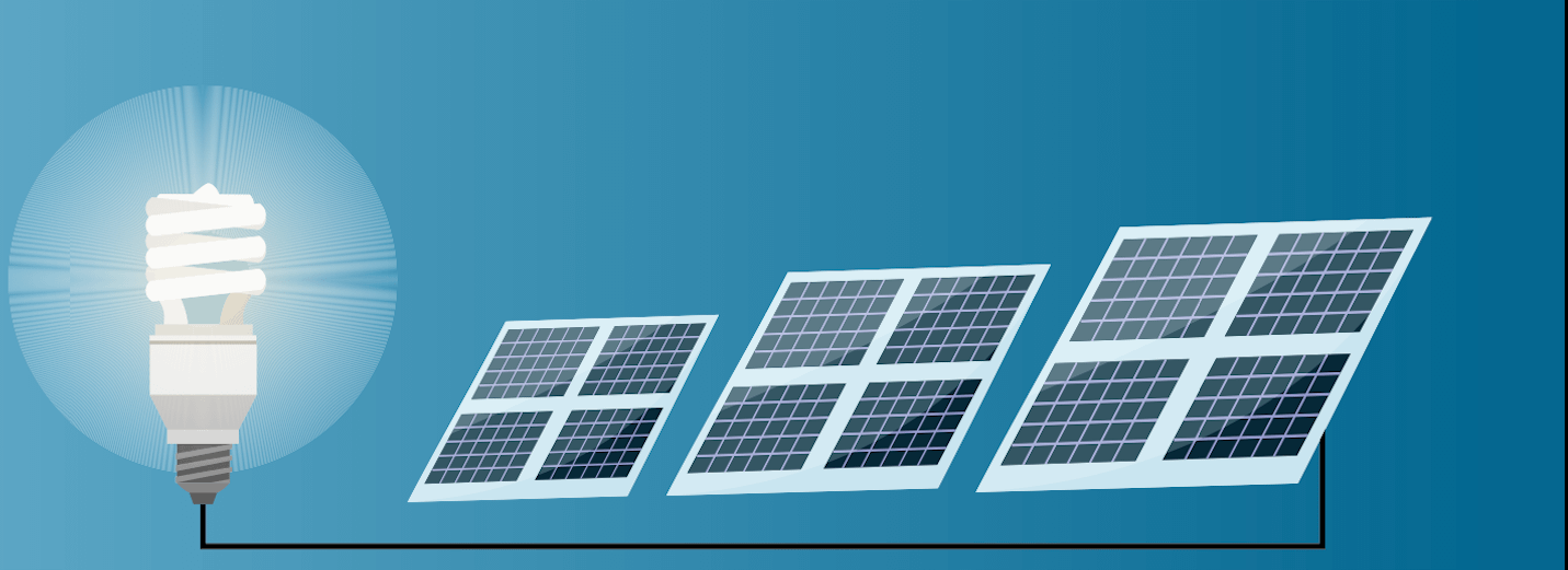
Are you ready to learn solar?! In this edition we give you a quick and dirty walk through of solar photovoltaic (PV) power generation; from photon to to outlet. Bookmark this post and use it as the jumping off point to our other articles which will teach you how to size the components we discuss here. You’ll find links to those articles hyperlinked along the way and also summarized at the bottom of the post.
For example, if you want to learn how many panels you’ll need for your off-grid system, click here.
Use the hyperlinked table of contents below to jump around to the topic of your choice.
Kissed by the Sun
As we all know, the solar generation process begins with that giant nuclear fusion reactor in the sky. The orb we all love to celebrate come summer time (or all year long if you’re so lucky), kisses the surface of our planet with intense energetic warmth every single day.
Solar Irradiance
Solar irradiance describes how much of the sun’s power lands in a particular time and place and is measured in watts per meter squared, or W/m2. Measured over time, we call it solar insolation. This value will determine how much power your panel(s) will produce where you live. After all, a square meter of earth’s surface in Los Angeles will receive more of the sun’s energy than a square meter in Seattle.
In order to compare solar panel output across geographical regions, panels are tested under controls called Standard Test Conditions, or STC. Among other STC requirements, solar irradiance is taken as 1,000 watts per square meter. This simulates the conditions on a nice, sunny day. The output under these conditions are referred to as your maximum power output rating. This is the output your panels are capable of achieving under basically ideal conditions.
POWER TO THE PEOPLE: THE ULTIMATE DIY SOLAR GUIDE FOR ENERGY INDEPENDENCE!
$10.99
Solar Panels
A Potential Difference
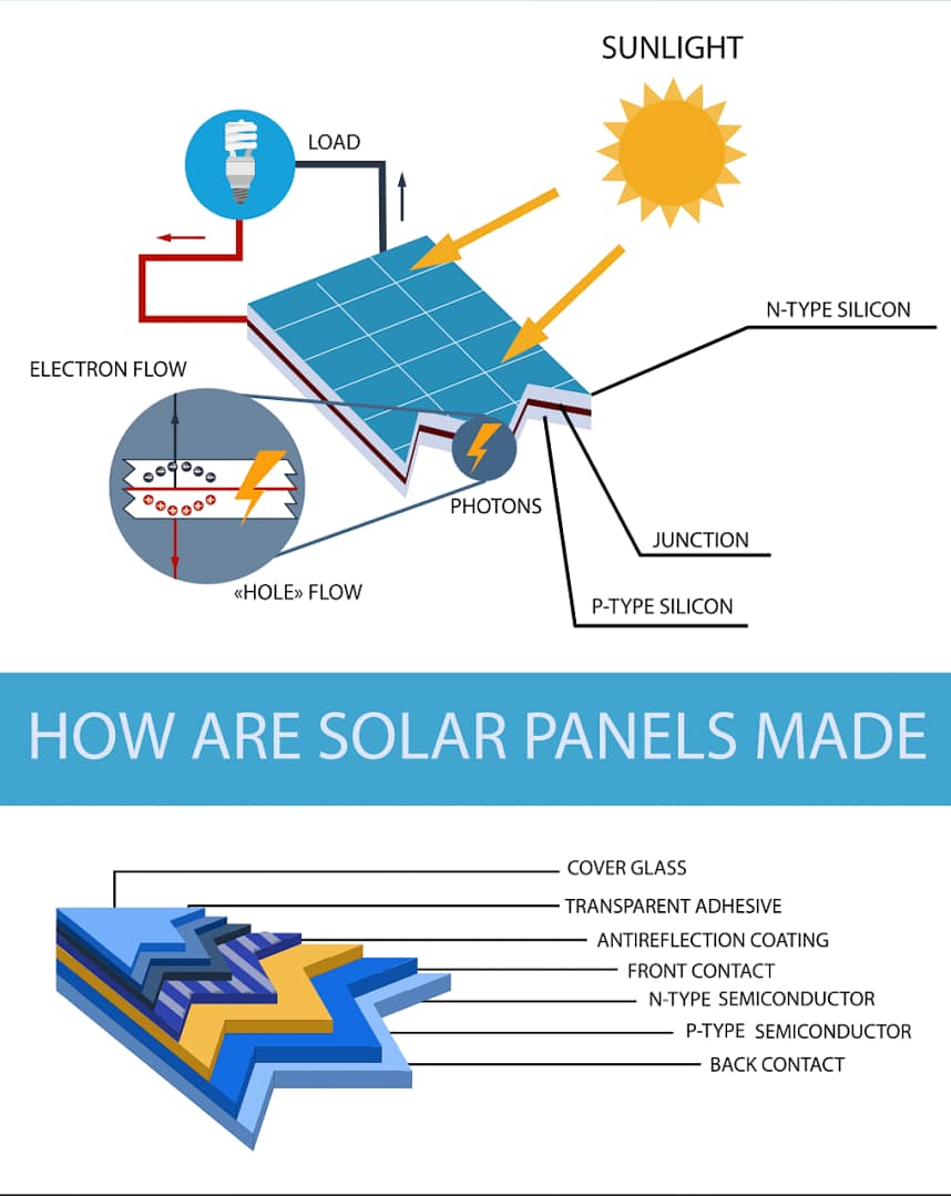
Most solar cells today are manufactured from silicon, which is the second most abundant element in the earth’s crust (oxygen takes the gold here). On its own, silicon isn’t very interesting from an electrical point of view. But once you dope it (yeah I said dope it) the silicon can be energized.
Electrons and Electron Holes
Doping a semiconductor means adding atoms to it which either adds electrons or creates what are called electron holes. Think of holes as voids where electrons want to be. In the figure above, the N-Type semiconductor layer has extra electrons and the P-Type semiconductor has an abundance of electron holes. (To learn more, check out the short video embedded at the end of this post)
For some reason, the image that comes to my mind for electrons and electron holes is Happy Gilmore telling his golf ball to go in its home. Something is wrong with me, I know. It’s not even a good analogy. An electron would happily jump into the hole. Let’s just call this an open circuit.
Note: As an affiliate, I earn from qualifying purchases.
Energy carrying photons from the sun penetrate the solar panel glass and liberate electrons on the N side. Those free electrons are repelled at the P-N junction, and make their way to the P side through your electrical circuit. This electron flow is also called electrical current, or what we colloquially refer to as electricity. Cool huh!
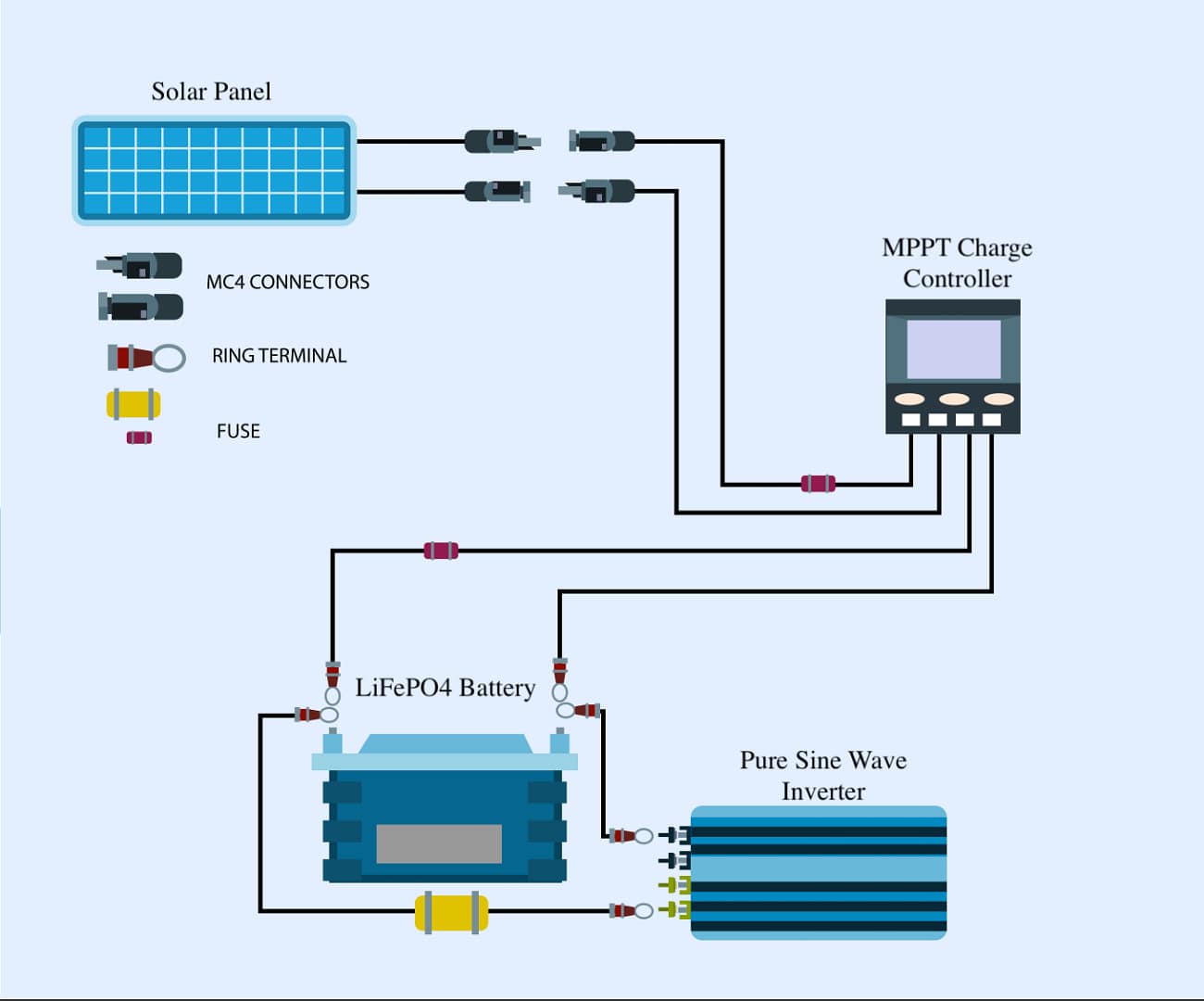
Charge Controller
Typical solar panels have a voltage rating of either 12 or 24 volts. That said, just as the power output of your solar panels fluctuates, so will the voltage output. A 12 volt solar panel can potentially produce a voltage approaching nearly 20 volts. If you applied that much voltage to a 12 volt battery you could damage your equipment or create a very unsafe condition.
To prevent this, and to optimize the output of your panel(s) a charge controller is used. Charge controllers are typically either pulse width modulation (PWM) or Maximum Power Point Tracker (MPPT) controllers. While PWMs can be acceptable for small applications, you want to be using an MPPT to power most of your electronics. They are a little more expensive, but well worth the upgrade and cheaper in the long run.
The Distance Analogy
While we have articles dedicated to sizing the other solar PV system components, the same is not true for charge controllers, so we’ll cover a few important considerations here. When selecting a charge controller you need to make sure it’s compatible with the rest of your system.
Voltage
The controller receives power from your solar panels and delivers it to your battery bank. So, the MPPT input voltage needs to be able to handle the voltage output from your solar panel array. And the MPPT output needs to match the nominal voltage of your battery bank.
Note: As an affiliate, I earn from qualifying purchases.
Make sure you understand the implication of arranging your solar panels in series verses parallel for this consideration. If combining panels in series, the voltages will add. So, four 12 volt panels in series will give you a 48 volt output. However, if the same panels were combined in parallel, the voltage would remain at 12 volts for the whole array with an increase in current accounting for the added power. Consider this when designing and sizing your system.
Amperage
A simple way to calculate the current rating for your controller is to take the power output of your panels and divide by the nominal voltage of your system.
For example, if the power output of the panels on your array add up to 1000 watts and the voltage of your battery bank or inverter input is 24 volts, then the rated max output would be 41.67 amps.
P = I * V => I = P / V
I = 1000w / 24v
I = 41.67 amps
Notice, because the voltage is in the denominator, decreasing the nominal voltage of your system will proportionally increase the current, and vice versa.
Once again, we should apply a safety factor of about 25%. A 50 amp controller would be acceptable for this case.
Battery
If you have a battery backup for your system, this will be the next piece of equipment in the path of those flowing electrons. Electrons will either park in your battery, converted for later use, or if needed now, they’ll continue through the rest of your system, powering any circuits along their way to cozy electron holes back at the solar panels.
For more on batteries for your solar system check out our article on sizing your off-grid battery bank.
LiFePO4 – Lithium Ion – Lead Acid
At the moment, lithium iron phosphate is the go-to for your DIY solar system energy storage. In the evolution of solar system battery banks, lead acid was improved on with lithium ion batteries. The more energy dense solution required less maintenance, improved life span and increased the depth-of-discharge in comparison to their lead acid predecessors.
Note: As an affiliate, I earn from qualifying purchases.
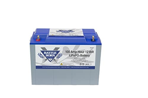
Battle Born Batteries LiFePO4 Deep Cycle Battery – 100Ah 12v Lithium Battery
$925.00
Lithium iron phosphate offers even more improvement. LiFePO4 batteries are slightly less energy dense than their lithium ion counterparts. While this does make their overall footprint a bit larger that probably isn’t much of a consideration for an off-grid or on-grid energy storage system. The chemistry in LiFePO4 is more stable and eliminates the explosive hazards associated with lithium ion. LiFePO4 batteries are also cheaper, they last longer and allow an ever deeper depth-of-discharge.
Safety First
Of all the components in your system, the battery bank can be particularly hazard prone. If you’re looking for places to save money in your system, I suggest you look elsewhere. Unless you know what you’re doing, don’t build it yourself, or try to Frankenstein some bank of caste off batteries together. Find quality LiFePO4 batteries, don’t mix and match, take good care of the bank and it will be there to safely hold on to your extra electrons for you for years to come. While there are many quality options out there, I recommend Battle Born.
Inverter
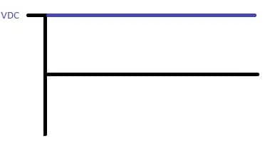
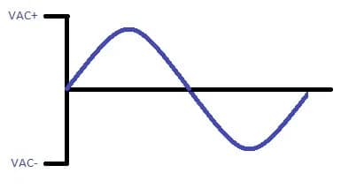
Up to this point our electrons have been flowing in one direction, or direct current (DC). But the outlets we plug our devices into want electrons rapidly flowing back and forth, or alternating current (AC). Your inverter is the component that directs this traffic.
If you want to brush up on your understanding of AC and DC check out the discussion in our Say Watt?! article. To learn how to size your solar system inverter check out our inverter sizing article.
Note: As an affiliate, I earn from qualifying purchases.
Victron Energy MultiPlus-II 2X 120V, 3000VA 12-Volt Pure Sine Wave Inverter and 120 amp Battery Charger
$1,491.08 Original price was: $1,491.08.$1,416.95Current price is: $1,416.95.
Breaking this down to the most basic concept – a DC signal goes into your inverter, an AC signal comes out. On an oscilloscope, the transition would go from a flat(ish) looking line, to the wavy line you see below, assuming you are using a pure sine wave inverter. There are exceptions, but generally speaking you will want a pure sine wave inverter. You can damage your electronics or create other issues if you try to save money by using a modified sine wave inverter.
Cable and Fuse Sizing
This part of your circuit design is all about safety. Your cables and other components need to be capable of carrying the highest current it will possibly see. Ever. To be absolutely certain this is the case, you need to protect your circuit with a protective device (e.g. fuse or breaker). This protective device needs to be sized so that it will interrupt the circuit by creating an open circuit condition (lean more here) in response to any level of current approaching the limits of your design.
Note: As an affiliate, I earn from qualifying purchases.
Designing for Maximum Current
Max current is the total power draw possible on that circuit divided by the nominal voltage at that point in the system. This isn’t always as straight forward as it sounds. At startup, motors have inrush current that may be multiple times the operating current, which needs to be accounted for. Equipment that will operate continuously or for more that 3 hours at a time need to be sized even larger to account for accumulated heat build up. The goal is to protect against fire. As such, these rules and regulations are under the purview of the National Fire Protection Association (NFPA) and administered per their National Electrical Code (NEC). More on this later.
Once you’ve identified your circuit’s max current, apply a safety factor, then size your cable accordingly. A safety factor of 20% is a minimum. The higher your safety factor, the safer you are; however, a higher safety factor also increases the cost of your components, so there is a tradeoff to consider.
Example: Assume you’ve calculated that your circuit will see a maximum of 10 amps. Applying a safety factor of 20% means that your cable will be rated for 12 amps. 10 amps x 120% (or, 1.2) = 12 amps.
Never allow your cable to become the fuse
A helpful way to think about cable sizing is that you never want a wire to become a fuse. That’s your fuses job. Size all of your components to safely carry all the current you might need. Then size your protective device (e.g. the fuse) to fail before anything else in the circuit.
In summary: identify the highest current you need to protect against, apply a safety factor, size your protection to fail before any other circuit components. This means cabling, connectors, switches and all other components in your circuit are sized to accommodate more current than your fuse is rated for. DO NOT LET YOUR CABLE BECOME THE FUSE!
National Electric Code (NEC)
Definitely consult the National Electric Code (NEC). And definitely consult a professional if needed. Electricity can be unforgiving, so please be safe.
Video Wrap Up
Check out the video below for a great illustration of the hole – electron interaction.
Video Credit: Lesics
Summary
In this edition we’ve covered the life of electrons flowing through your solar PV system, from photon to light bulb and back again. We covered the basics of all the components in your system.
If you’re ready to start sizing your solar PV system, we have you covered. Follow the links below:
Evergreen Off-Grid Approved Resources
Note: As an affiliate, I earn from qualifying purchases.
Thank You!
Thank you for checking out Evergreen Off-Grid! The great thing about the internet is we can edit and update these articles any time! Don’t be shy. Just toss your questions in the chat and help us make this blog series as useful as possible. We are standing by to answer your questions! We are your personal electrical engineer. If you enjoy our content please like, subscribe and share with your friends!
As a reward for engaging with us, we’re sending the first 10 readers to leave a relevant comment in our Learn Solar blog series (this qualifies!) a FREE copy of our first edition print of “POWER TO THE PEOPLE: THE ULTIMATE DIY SOLAR GUIDE FOR ENERGY INDEPENDENCE!” mailed anywhere in the Continental United States. Just comment, then send your mailing information to info@evergreenoffgrid.com. That’s it!