
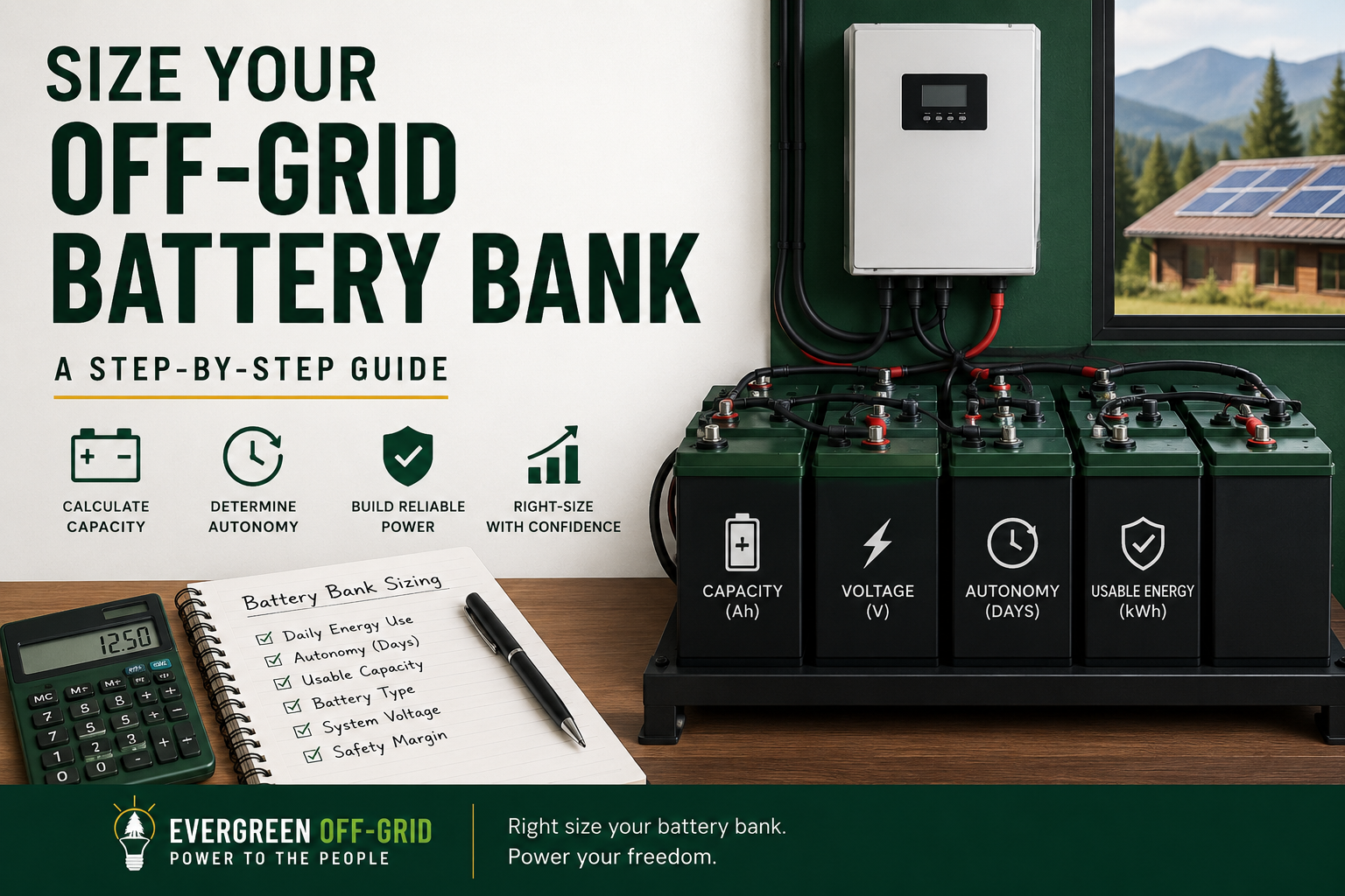
An off-grid battery bank must store enough energy to run your electrical loads when solar production is unavailable or insufficient. Proper sizing requires more than dividing daily energy use by battery voltage: you must also account for the desired days of autonomy, usable depth of discharge, conversion losses, battery reserve and the limitations of the selected equipment.
This guide explains how those factors work together and provides a step-by-step method for estimating nominal battery capacity. If you already know your expected loads, you can also use the Free System Designer to calculate your battery bank, solar array, inverter and charge-controller requirements.
How Much Battery Storage Do You Need?
Battery-bank sizing begins with your average daily energy consumption, measured in watt-hours or kilowatt-hours per day. That value tells you how much usable energy the battery must deliver during a typical operating day.
Days of Autonomy
Days of autonomy describe how long the battery bank is intended to support your loads with little or no solar production. There is no single autonomy target that is appropriate for every off-grid system.
- One day reduces initial cost but provides limited protection from poor weather or unexpected energy use.
- Two days provides a more conservative reserve for many preliminary designs.
- Three or more days may be appropriate for critical loads, remote locations or systems without reliable generator backup.
The right value depends on seasonal weather, load criticality, acceptable outage risk, generator availability and budget. Increasing autonomy can quickly make the battery bank one of the most expensive parts of an off-grid system, so it should be selected deliberately rather than treated as a universal rule.
Battery chemistry also affects the amount of installed capacity that is usable. Lead-acid and lithium iron phosphate batteries have different depth-of-discharge limits, efficiencies, maintenance requirements and operating characteristics. Those differences must be included when converting required usable energy into nominal battery capacity.
Lead-Acid Batteries
Lead-acid batteries remain available for off-grid systems because they generally cost less initially than lithium batteries. However, they are heavier, less efficient and usually provide fewer usable cycles. Flooded lead-acid batteries also require periodic maintenance and appropriate ventilation.
Use batteries designed for deep-cycle service—not automotive starting batteries. Starting batteries are built to deliver a brief burst of high current and are not intended for repeated deep discharge. Common off-grid lead-acid options include flooded deep-cycle, absorbed glass mat (AGM) and other purpose-built renewable-energy batteries.
Many lead-acid designs are operated at approximately 50% maximum depth of discharge to preserve service life, although the correct limit must come from the battery manufacturer. Installing additional capacity reduces the depth of each cycle and may extend battery life, but additional autonomy should still be selected primarily around reliability, weather, generator availability and cost.

HQST LiFePO4 Battery 100ah Lithium Battery
$179.99
Depth of Discharge
Depth of discharge (DoD) describes the percentage of a battery’s nominal capacity that has been removed. State of charge (SoC) describes the percentage remaining. For example, a battery at 80% depth of discharge has approximately 20% state of charge remaining.
Depth of discharge directly affects usable storage. A 10 kWh battery operated to a maximum of 80% DoD provides approximately 8 kWh of usable energy before accounting for conversion losses and reserve margin.
Always use the battery manufacturer’s recommended design limit. Regularly exceeding that limit can shorten battery life or trigger the battery-management system. Installing additional capacity reduces the depth of each cycle and can provide room for aging, unexpected energy use and changing operating conditions.
Lithium Iron Phosphate (LiFePO4) Batteries
Lithium iron phosphate (LiFePO4) batteries are widely used in modern off-grid systems because they provide high usable capacity, good round-trip efficiency, relatively long cycle life and less routine maintenance than flooded lead-acid batteries.
Most LiFePO4 batteries include a battery-management system (BMS) that protects against excessive charge current, discharge current, voltage and temperature. The BMS is a final protective limit—not a substitute for designing the system within the manufacturer’s recommended operating ratings.
Many LiFePO4 manufacturers permit approximately 80% or more depth of discharge, but the appropriate design value must come from the selected battery’s documentation. Maximum allowable discharge is not necessarily the same as the recommended value for routine use.
Usable Capacity and Installed Capacity
A battery’s nameplate rating represents nominal capacity, not necessarily the energy available to the loads. For example, a 12.8 V, 100 Ah battery stores approximately 1.28 kWh of nominal energy:
12.8 V × 100 Ah = 1,280 Wh, or 1.28 kWh
At an 80% design depth of discharge, that battery provides approximately 1.02 kWh of usable DC energy before accounting for inverter and wiring losses. Because LiFePO4 batteries typically allow a greater usable percentage than lead-acid batteries, fewer nominal amp-hours may be required for the same usable energy target.
Compare battery options using usable kilowatt-hours, recommended operating limits, cycle life, warranty and total installed cost—not nameplate amp-hours alone.
Temperature and Current Limits
Battery temperature limits are especially important in off-grid installations. Many LiFePO4 batteries must not be charged below freezing unless they include internal heating or low-temperature charge protection. Discharge and storage limits may be different, so verify the manufacturer’s specifications for the expected installation conditions.
The battery bank must also provide enough continuous and short-duration current for the inverter. Confirm the recommended and maximum BMS charge and discharge ratings, the allowed number of batteries in parallel and the inverter’s expected DC input current before finalizing the design.
Step-by-Step Battery Bank Sizing Example
The following example shows how daily electrical energy becomes a battery-capacity requirement. This simplified cabin load profile consumes 3,380 Wh, or 3.38 kWh, during a representative high-use day.
When preparing your own load profile, include each appliance’s wattage, quantity and expected operating time. Use a realistic high-use day rather than an unusually light day, and account for cycling equipment such as refrigerators and pumps using an appropriate duty cycle.
The free calculator performs this load calculation automatically, but the example below shows the underlying process.
| Load | Watts | Hours/ day | Daily energy |
|---|---|---|---|
| Refrigerator | 50 W | 24 | 1,200 Wh |
| TV | 50 W | 4 | 200 Wh |
| Computer | 50 W | 4 | 200 Wh |
| Interior lighting | 100 W | 5 | 500 Wh |
| Exterior lighting | 100 W | 12 | 1,200 Wh |
| Phone charging | 20 W | 4 | 80 Wh |
| Total | 3,380 Wh 3.38 kWh |
Calculating Total Daily Energy
Add the daily energy for each load to determine the system’s total daily consumption. In this example:
1,200 + 200 + 200 + 500 + 1,200 + 80 = 3,380 Wh/day, or 3.38 kWh/day.
This value represents the electrical energy the battery bank must supply during a representative high-use day. Loads not included in the table—such as heating, air conditioning, water heating, pumps or cooking appliances—must be added if they will operate from the off-grid system.
Use realistic operating times and account for equipment that cycles on and off. A refrigerator, for example, may be represented by its measured daily energy consumption or by an appropriate average duty cycle rather than its full rated wattage for 24 continuous hours.
Selecting Battery-Bank Voltage
Battery-bank voltage affects inverter compatibility, DC current, conductor size and the way individual batteries or modules are arranged. Common nominal system voltages include 12 V, 24 V and 48 V.
Higher-power systems generally benefit from a higher battery-bank voltage because delivering the same power at a higher voltage requires less current. The voltage must be selected to match the inverter and other DC equipment; it is not determined solely by battery capacity.
For the remainder of this example, assume a nominal 48 V battery bank assembled from compatible nominal 12 V batteries.
Combining Batteries in Series
Connecting compatible batteries in series increases voltage while the amp-hour capacity remains unchanged. Connect the positive terminal of one battery to the negative terminal of the next.
For example, four nominal 12 V, 100 Ah batteries connected in series create a nominal 48 V, 100 Ah battery bank:
12 V × 4 batteries = 48 V nominal
100 Ah remains 100 Ah
Only connect batteries in series when the manufacturer permits it. Use matching batteries with the same model, capacity, age and state of charge, and confirm that each battery’s management system supports the intended series configuration.
Combining Batteries in Parallel
Connecting compatible batteries or complete series strings in parallel keeps the voltage unchanged while increasing amp-hour capacity and stored energy.
For example, two identical 48 V, 100 Ah series strings connected in parallel create a nominal 48 V, 200 Ah battery bank:
48 V remains 48 V
100 Ah × 2 parallel strings = 200 Ah
Parallel strings should use matching batteries and balanced conductor lengths so current is shared as evenly as practical. Follow the manufacturer’s limit on parallel batteries or strings, and provide the required overcurrent protection and disconnecting means for each string.
Why Battery-Bank Voltage Matters
Electrical power is the product of voltage and current:
Power (W) = Voltage (V) × Current (A)
For the same power, increasing the battery-bank voltage reduces the required DC current. Before accounting for inverter losses, a 3,000 W load would draw approximately:
- 250 A from a 12 V battery bank
- 125 A from a 24 V battery bank
- 62.5 A from a 48 V battery bank
Lower current can reduce conductor size, voltage drop and electrical losses, which is why 48 V battery banks are common in larger off-grid systems. However, every battery, inverter, charge controller and DC load must be compatible with the selected nominal voltage.
The example below uses 48 V to demonstrate the sizing calculations. Final voltage selection must be based on the actual equipment and system requirements.
Converting Daily Energy to Amp-Hours
Battery capacity is often expressed in amp-hours, but an amp-hour value is meaningful only when the battery-bank voltage is also stated. Convert daily energy to equivalent amp-hours using:
Amp-hours (Ah) = Energy (Wh) ÷ Battery-bank voltage (V)
For the 3,380 Wh/day example at a nominal 48 V:
3,380 Wh ÷ 48 V = 70.4 Ah
The loads therefore require the equivalent of approximately 70.4 Ah at 48 V for one representative day. This is only the base energy requirement. It does not yet account for days of autonomy, allowable depth of discharge, conversion losses, reserve margin, battery aging or equipment limitations.
Disclosure: As an affiliate, Evergreen Off-Grid may earn a commission from qualifying purchases at no additional cost to you.
Off-Grid Batteries
Applying the Depth-of-Discharge Limit
The required nominal battery capacity must be larger than the energy you intend to use because batteries should not necessarily be discharged through their entire rated capacity. Use the selected battery manufacturer’s recommended depth-of-discharge value.
For this example, assume a LiFePO4 battery with a recommended design depth of discharge of 80%:
70.4 Ah ÷ 0.80 = 88.0 Ah
The example therefore requires at least 88 Ah of nominal capacity at 48 V to provide one day of usable energy before accounting for conversion losses, reserve margin, battery aging or additional days of autonomy.
A maximum allowable depth of discharge is not necessarily the appropriate value for routine design. Follow the manufacturer’s recommended operating limit for the selected battery.
Days of Autonomy
Days of autonomy describe how long the battery bank should support the loads with little or no solar production. More autonomy increases resilience, but it also increases battery-bank size and cost.
For this example, use two days of autonomy:
88.0 Ah/day × 2 days = 176 Ah at 48 V
The example therefore requires at least 176 Ah of nominal battery capacity at 48 V after applying the assumed 80% depth-of-discharge limit. Conversion losses, reserve margin, aging and equipment-specific limitations still need to be considered before selecting the final battery quantity.
Two days is a planning assumption—not a universal requirement. The appropriate value depends on seasonal weather, load criticality, generator availability, acceptable outage risk and budget.
Selecting the Number of Batteries
Battery capacity must be converted into an actual quantity of compatible batteries or modules. For this simplified example, assume nominal 12 V, 100 Ah batteries that the manufacturer permits to be connected in the required series and parallel arrangement.
The previous calculation produced a minimum requirement of 176 Ah at 48 V. Assuming approximately 90% battery-to-load delivery efficiency:
176 Ah ÷ 0.90 = 195.6 Ah at 48 V
The battery bank must therefore provide at least approximately 196 Ah at 48 V. Because the selected batteries create complete 100 Ah series strings, the result must be rounded up to the next achievable configuration.
Combine in Series
Each complete 48 V series string requires four nominal 12 V, 100 Ah batteries:
4 batteries × 12 V = 48 V nominal
Connecting the four batteries in series produces one 48 V, 100 Ah string. Series connections increase voltage, but the string’s amp-hour capacity remains 100 Ah.
Combine in Parallel
The calculated requirement is approximately 196 Ah at 48 V. Because each complete series string provides 100 Ah, divide the required capacity by the capacity of one string and round up:
195.6 Ah ÷ 100 Ah/string = 1.956 strings
Round up to two parallel strings. Together, the two strings provide a nominal battery-bank capacity of:
48 V × 200 Ah = 9,600 Wh, or 9.6 kWh nominal
At the assumed 80% depth of discharge, this bank provides approximately 7.68 kWh of usable stored energy before accounting for delivery losses.
Example Battery-Bank Result
The example requires two parallel strings, with each string containing four nominal 12 V, 100 Ah batteries in series.
- Total batteries: 8
- Configuration: 4 batteries in series × 2 parallel strings (4S2P)
- Nominal battery-bank voltage: 48 V
- Nominal capacity: 200 Ah
- Nominal stored energy: 9.6 kWh
- Usable energy at 80% DoD: approximately 7.68 kWh
- Estimated delivered energy at 90% efficiency: approximately 6.91 kWh
The two-day load requirement is 6.76 kWh, so this configuration satisfies the simplified assumptions—but with very little additional reserve. A final design may require more capacity for battery aging, temperature, unexpected loads, future expansion or a larger design margin.
The selected batteries must also support the required series and parallel configuration, charge and discharge current, environmental conditions and communication requirements of the complete system.
Battery Sizing and Inverter Sizing Are Different
Battery-bank sizing is primarily based on energy consumption, measured in watt-hours or kilowatt-hours. Inverter sizing is based on power demand, measured in watts.
The inverter must support the maximum realistic combination of loads expected to operate simultaneously. It must also provide adequate short-duration surge capability for equipment such as refrigerators, pumps, compressors and power tools.
- Battery bank: sized from daily energy use, autonomy, depth of discharge, efficiency and reserve
- Inverter: sized from simultaneous running watts and starting or surge watts
Do not depend on routine inverter overload trips as a method of load management. If certain loads must not operate together, use documented operating procedures, controls or load-shedding equipment.
The battery bank and its management system must also be capable of supplying the inverter’s required continuous and surge DC current. Verify battery discharge ratings, parallel limits, conductor ampacity, voltage drop and overcurrent protection before finalizing the design.
Summary
Off-grid battery-bank sizing begins with a realistic estimate of daily electrical energy use. That energy requirement is then adjusted for battery-bank voltage, days of autonomy, allowable depth of discharge, conversion losses and the available sizes of compatible batteries or modules.
In the simplified example, a 3.38 kWh daily load with two days of autonomy resulted in a preliminary battery bank of:
- 48 V nominal
- 200 Ah nominal capacity
- 9.6 kWh nominal stored energy
- Eight nominal 12 V, 100 Ah batteries arranged 4S2P
This is a planning example, not a final construction design. Final equipment selection must verify manufacturer connection limits, battery-management-system ratings, inverter current, conductor sizing, overcurrent protection, disconnecting means, grounding, environmental conditions and applicable electrical codes.
To evaluate your own loads and design assumptions, use the free Evergreen Off-Grid System Designer.
Questions About Your Battery-Bank Design?
Join the Evergreen Off-Grid Newsletter
Practical DIY solar tips, new calculators, and gear picks—about 1–2 emails a month. No spam. Unsubscribe anytime.
By submitting this form, you are consenting to receive marketing emails from: . You can revoke your consent to receive emails at any time by using the SafeUnsubscribe® link, found at the bottom of every email. Emails are serviced by Constant Contact