In this edition we’re going to get you completely indoctrinated into the basic tech speak you need to know to understand solar. Maybe you want to be better informed while you evaluate solar bids. Or, maybe you want to sharpen your understanding before you dig into some DIY. Either way, we’ve got you covered. You don’t need to be an engineer to understand the basics. All you need is a few minutes with this article. Once you grasp these concepts, you’ll be talking solar in no time.
Welcome to our Electrical Cheat Sheet!
Use the hyperlinks below to jump to the topic of your choice or read through the whole article. Bookmark this article for later use. This article is intended to serve as your quick reference for solar engineering terms. And to make this article even more useful, we’re here to answer all your comments if you just enter them below the article. We can add to the article, we can clarify any topics, or even write a whole new article if your question is good enough… Yeah, that’s a challenge.
The Nuts and Bolts of Amps and Volts
Let’s dig into the nuts and bolts, shall we? We’ll begin by defining 3 units:
- Volt
- Ampere
- Resistance
The most common analogy used when teaching how these units interact is water flowing through a pipe. In this analogy, the voltage represents the pressure. The resistance represents the size of the pipe. And the current represents the amount of water flowing through the pipe.
Volts
Measuring voltage is similar to measuring the pressure at one end of a pipe and comparing it to the pressure at the other end. For water to flow through the pipe, there has to be a difference in pressure. If the pressure were the same throughout the pipe, the water would sit stagnant. The same is true for voltage in a circuit. If the voltage is the same between two connected points, then there is a potential difference or voltage difference of zero. So, it would be appropriate to say there are 0 volts between those points. Even if both points happen to have a voltage difference with reference to ground.
A Potential Difference
With voltage what we’re interested in really, is the voltage difference. We care about the voltage of something with respect to the voltage of something else. Consider a height measurement, for example. If you were measuring me, you would be measuring the top of my head with respect to the bottom of my feet. Simple enough.
Now, suppose I pointed to a random place above the ground and said, “how high is that?” Naturally, you would assume that I meant, “what is the distance in height between that point and the ground level beneath it.” Coincidentally, ground is also the standard reference point when talking about voltage level. But the height of that point in the sky can be measured with respect to anything. I could have been asking how high the point was with respect to sea level. That would change my answer, unless we happened to be at the beach. Conversely, I could have been asking how high the point was from my roof, or from my porch. You get the idea.
The same is true with voltage. It’s true meaning comes from its relationship to another point. When we say we’ve measured a voltage level, we’ve really measured a voltage difference, or a potential difference.
📘 POWER TO THE PEOPLE
The ultimate DIY solar guide for energy independence!
By Jon Springer, PE
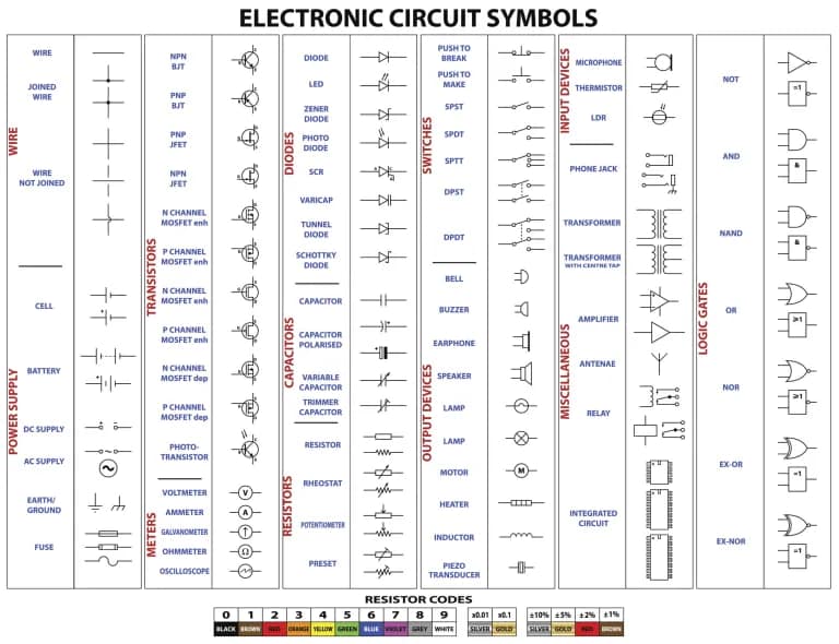
👉 Get it on AmazonBonus! Electronic Circuit Symbols Cheat Sheet
Amperage
Amperage, or current, is a measurement of the amount of electricity flowing through a given point. This is the simplest variable to understand in my mind. In our pipe analogy, current flow is water flow. It is the essential stuff we are moving and using. A current measurement tells us how much of our essential stuff, electricity, is flowing as time passes along.
Resistance
Often referring to your load, or what you have plugged in, resistance is anything that dissipates energy in your circuit. Often, that energy is used in whatever device you’re powering, so that device becomes a “resistor” in your circuit. Unfortunately, our cables and wires also offer a small resistance, so energy is dissipated there, and in other components as well, in the form of heat. If your wires or equipment aren’t sized appropriately that heat loss can become fire.
Resistance is similar to the diameter of the pipe in our analogy. Obviously, a larger pipe would allow more water to flow through it and a smaller pipe less. Thus, a smaller pipe offers more “resistance” to the water flowing through it. Similarly, your electronic device is seen by your power source as a resistance. It is a throttle on the flow of current through your circuit.
Dividing by Zero
When we were first taught division, our teachers said we couldn’t divide by zero. If you stuck around long enough you learned that this isn’t exactly true. Mathematicians like to hedge their bets on this and say instead that the solution to dividing by zero trends towards infinity.
Go ahead and try it. Open your calculator app, enter a number and divide it by progressively smaller numbers and you’ll see that it’s true. Take the following table for example:
| 1/X | Equals |
| 1/1 | 1 |
| 1/0.1 | 10 |
| 1/.01 | 100 |
| 1/0.000001 | 1,000,000 |
A short circuit simply means that you’ve created a direct, low resistance path. Now, let’s rearrange Ohm’s Law to solve for current:
I = V/R
As our resistance approaches zero, or shorts out… current approaches infinity. Fortunately, long before reaching infinity your components blow up and start a fire. I say fortunately, because I’m not sure what happens at infinity… maybe that’s where black holes come from. But I digress.
The point is, the power is dissipated in your wires in the form of heat. The level of heat is proportional to the amount of power dissipated. Specifically, the heat energy liberated is the square of the current times the resistance or I2 * R. So, as current (I) “approaches infinity” you’re generating a ton of heat, which can start fire.
Power
While Ohm’s Law is interesting and super critical to understanding electrical engineering, I’m going to leave it there and move to another measurement that will be critical to you when sizing system components in your solar photovoltaic (PV) system. The equation I’m referring to describes the relationship between Power, Voltage and Current.
Power = Voltage * Current, or, P = I * V
Because V is usually fixed (120 VAC in your home, for example), current and power usually track with each other. As one rises or falls, so does the other. If you know one value, you can find the other.
For example, if I measured 1 amp (I) flowing in my equipment operating at 120 volts (V), I know that device is consuming 120 W (P).
I * V = P => 1 Amp * 120 Volts = 120 Watts
Or, if I have a 12 Watt (P) LED lightbulb plugged into a 120 volt (V) circuit, then I know that lightbulb is drawing 0.1 Amps (I).
I * V = P => P/V = I => 12/120 = I = 0.1 Amps.
Wire Sizing
The National Electric Code (NEC) governs wire sizing and is primarily concerned with current carrying capacity in the wire sizing tables. The NEC is actually produced by the National Fire Protection Administration (NFPA). It may seem strange that the NFPA is the authority on electrical safety, but remember, fire is a primary hazard when it comes to electricity.
It’s helpful to think of current level as being the main culprit when it comes to fire, as we can see in our I2 * R heat losses described above. So knowing that your wires are sized to handle the highest possible current draw they might see is critical.
Again, it’s important to stress that incorrectly sizing any parts of your electrical system is incredibly dangerous and can have disastrous consequences. Please be sure all electrical design and construction is performed by a qualified person.
Power (W) vs Energy (Wh)
Mixing up kilowatts and kilowatt-hours is a common cause of confusion. So, let’s clear up the difference between power and energy.
Power, measured in Watts, is an instantaneous measurement. The measurement tells you how much electricity is being produced or consumed in a moment in time. You’re interest in power when it comes to solar will often be in regard to equipment rating. That is, how much power can this equipment handle in a given moment. Your inverter is a good example of this. When sizing your inverter, you’ll need to make sure it’s rated to handle the maximum possible power level it may be subjected to.
Energy, usually measured in watt-hours (or watts times hours), is a cumulative measurement. It’s the sum of all power measurements over a given period of time, which is almost always taken as an hour. Your electricity bill (if you have one) charges you by the kilowatt-hour (a thousand watt hours). If you want to know how much energy you use in a day, or year, check your electricity bill. For some prospective, the average American home consumes about 30 kwh every day.
The Distance Analogy
The most common analogy used to describe the relationship between power and energy is the relationship between speed and distance. In this case power is the “speed” and energy the “distance.”
If I travel at 10 miles per hour for an hour, I will have traveled 10 miles.
Similarly, if I consume 10 watts of energy for an hour, I will have consumed 10 watt-hours in an hour.
So just like speed, power describes a rate of change. And just like distance, energy describes the total change over a period of time.
Watt-hour
A watt-hour is the amount of energy consumed in 1 hour, by a device that is constantly consuming 1 watt. So, if I have a 100 watt device running for an hour, I’ve consumed 100 watt-hours of energy in that hour. If I run that device for 4 hours it will consume 400 watt-hours of energy. A 372 watt device will consume 372 watt-hours in a single hour. See the pattern?
Amp-hour
As we discussed above, voltage is typically a set value. As a result, current and power track each other. So, talking about the current draw of a device is very similar to talking about its power consumption. As a result, watt-hours and amp-hours are both used to describe energy consumption.
An amp-hour is calculated in the same way a watt-hour is. A device drawing 1 amp for 1 hour will draw 1 amp-hour of current.
A device drawing 2 amps for a half hour, then 4 amps for the next half hour will draw a total of 3 amp-hours in that time span.
2 amps x 0.5 hours = 1 amp-hour
4 amps x 0.5 hours = 2 amp-hour
1 amp-hour + 2 amp-hour = 3 amp-hour
Your batteries will be rated in amp-hours. The amp-hour rating of a battery tells us its capacity. A 200 amp-hour battery (assuming its rated for 100% depth-of-discharge) will supply 2 amps for 100 hours, or 20 amps for 10 hours or any combination of amps and hours with a product of 200.
AC/DC
Understanding the power wave forms at different stages in your solar PV system is crucial. A wave form can be measured with a device called an oscilloscope, or o-scope. The o-scope will measure the parameter you select with respect to time.
Alternating Current
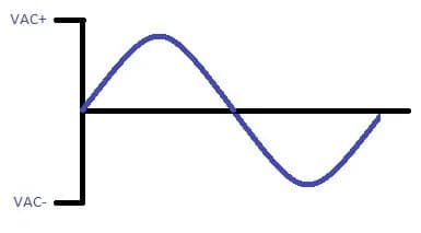
With alternating current (AC), the signal will bounce from a maximum to minimum. Technically, for the signal to be considered “alternating” it needs to cross from positive to negative in each cycle. This means the current is flowing in both the negative and positive directions.
The signal will sweep smoothly in the case of a pure sine wave (pictured left). If a cheap inverter is used (not recommended) you may have a choppier sine wave (pictured right), which introduces total harmonic distortion (THD), which is bad and can damage sensitive electronics.
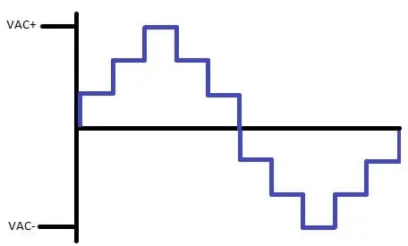
Alternating Current
The wall outlet in your home (if you live in America) offers 120V of alternating current. A pure sine wave sweeps from a value of positive 120 volts to negative 120 volts, 60 times every second (because our power grid operates at 60 Hz). Anything you plug into a standard wall outlet operates on 120VAC, 60Hz.
Direct Current
When direct current (DC) is measured with time it typically looks like a flat line. Technically, a signal is DC as long as it doesn’t change polarity, or change from positive to negative. So, it could sweep from some maximum to minimum positive or negative value as long as it doesn’t cross zero. But for our purposes, DC values will be mostly considered constant. Often at values of 6, 12, 24 or 48 Volts DC. With time measured on the X-axis, a DC signal would look like the figure below on an o-scope.
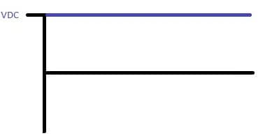
The output of your solar panels and your battery bank is DC. If you have special appliances or devices you can plug directly into DC you can use this power directly (no pun intended), assuming the voltage magnitude is appropriate.
However, as discussed above, anything that plugs into a standard wall outlet expects 120 VAC. So that DC signal generated by your panels and sitting at your battery bank will need to be modified into the usable 120 VAC. This is the job of your inverter.
Solar Panel Rating and Solar Irradiance
NASA does a pretty good job with its description of solar irradiance: Simply put, “Irradiance is the amount of light energy from one thing hitting a square meter of another each second.”
Let’s unpack that a little bit. When we’re shopping for solar panels we see them listed with a rated output power. I’ve seen a lot of confusion around this. Folks will be upset that their 200 watt panel is only producing 120 watts. There must be something wrong, right?
Wrong. Solar panel ratings are determined under what is called Standard Test Conditions, or STC.
Standard Test Conditions
STC (Standard Test Condition): Irradiance 1000 W/m², Module Temperature 25 °C (77 °F), AM 1.5
Each of these constants ensure we’re comparing apples to apples when looking at solar panel power output. Right at the beginning of this definition we see 1000 W/m². What this tells us is the panels are tested under conditions equivalent to 1,000 watts for every square meter tested.
Probably un-coincidentally, this is also the amount of energy provided by the sun for every square meter under what we call “Peak Sun” conditions, which we’ll discuss more below.
A light source with an energy output of 1000 watts per square meter is used in a laboratory to determine a panel’s power rating. This way a panel manufactured in Phoenix that is rated at 200 watts will have a similar power output as a solar panel manufactured in Seattle with an output of 200 watts. Without controlling these conditions, a panel in Phoenix would look more powerful simply because it’s exposed to a higher irradiance during testing.
So, will your 200-watt panel produce 200 watts? Sometimes, maybe. Think of the solar panel rating as an optimal output. If you have your panels under optimal conditions including location on earth, time of day, time of year, angle, clear skies, etc., then you may see a power output around the rated value. But as you get closer to dusk and dawn, and as the sun seasonally retreats and returns, or as you get closer or further from the equator, the output of your panels will vary.
Another measurement we use to help us determine the energy (watt-hours) our panels will produce is “Peak Sun Hours.” A peak sun hour is equal to 1,000 watts per square meter for an hour. However, it’s important to understand we aren’t only measuring moments when we actually have 1,000 watts per square meter on our panels. If conditions result in an average of 250 watts per square meter over 4 hours, then your panels were exposed to a total of 1 hour of peak sun during those 4 hours.
Peak sun hours are regionally dependent. Whereas a roof in Los Angeles can expect an average of 5.5 peak sun ours per day, a roof in Seattle will only get an average of 3.5 peak sun hours per day over the course of a year.
To convert peak sun to solar panel output, simply multiply your panels rating by the peak sun hours and you will get a rough estimate of the average amount of energy you will produce per day over a period of a year. Keep in mind, this estimate doesn’t include efficiency losses.
Also, peak sun is an average value. It will be larger in the summer and lower in the winter. So, if your panel is “underproducing” when you apply this peak sun measurement, consider the time of year.
Solar Irradiance vs Solar Insolation
The relationship between solar irradiance and solar insolation is similar to the relationship between power and energy. Insolation is quite simply a measurement of solar irradiance over time. Basically, this is just a fun fact.
Summary
What did I miss? Obviously, a lot… This is not a textbook. Nor is it intended to turn you into an electrical engineer. The point of this article is to serve as a basic reference or cheat sheet for anyone interested in solar and wanting to be more informed.
This article can also grow! Drop your ideas below. Tell me what you want covered in more detail, or other topics you’d like included. I can add to this edition, or if the question warrants I can put out a Part II to this article.
Please engage below and let us know what you think. How can this be improved? We want to hear from you! Contact us at info@evergreenoffgrid.com
Thank you for reading!

